Schlagwörter: TP link wrt 902
- Dieses Thema hat 480 Antworten sowie 33 Teilnehmer und wurde zuletzt vor vor 1 Tag, 1 Stunde von
 Eric aktualisiert.
-
AutorBeiträge
-
November 9, 2025 um 20:32 Uhr #5321
Hallo Torsten,
das Board hat einen Schiebeschalter „S1“, der schon verbaut ist.
Wenn Du einen gesonderten Schalter verbauen willst, musst Du diesen an J4 anschlissen.Beste Grüsse,
Eric
November 9, 2025 um 20:50 Uhr #5319Torsten, what I did was get the following from (US) Amazon:
https://www.amazon.com/dp/B0D5B82V6K
This connects to slave on-off control input (J5). When the switch is in the off position, a voltage here turns the unit on, and no voltage turns the unit off.
I then used a USB brick on a switched outlet to turn it off overnight for charging, and have it on during the day
Other elements for my build for the combo of the Ian Canada mini battery + Ian Canada conditioner + the WR902AC (since tracking these things down for a first build is a pain, hopefully there are equivalents from local options in Europe)
https://www.amazon.com/dp/B07PKKY8BX?ref=ppx_yo2ov_dt_b_fed_asin_title
https://www.amazon.com/dp/B0F9TP2GZ6?ref=ppx_yo2ov_dt_b_fed_asin_title&th=1
https://www.amazon.com/dp/B0CZ6WKTN5?ref=ppx_yo2ov_dt_b_fed_asin_title&th=1
https://www.amazon.com/dp/B09XWS2FTM?ref=ppx_yo2ov_dt_b_fed_asin_title&th=1
https://www.amazon.com/dp/B0CCRXF1N7?ref=ppx_yo2ov_dt_b_fed_asin_title
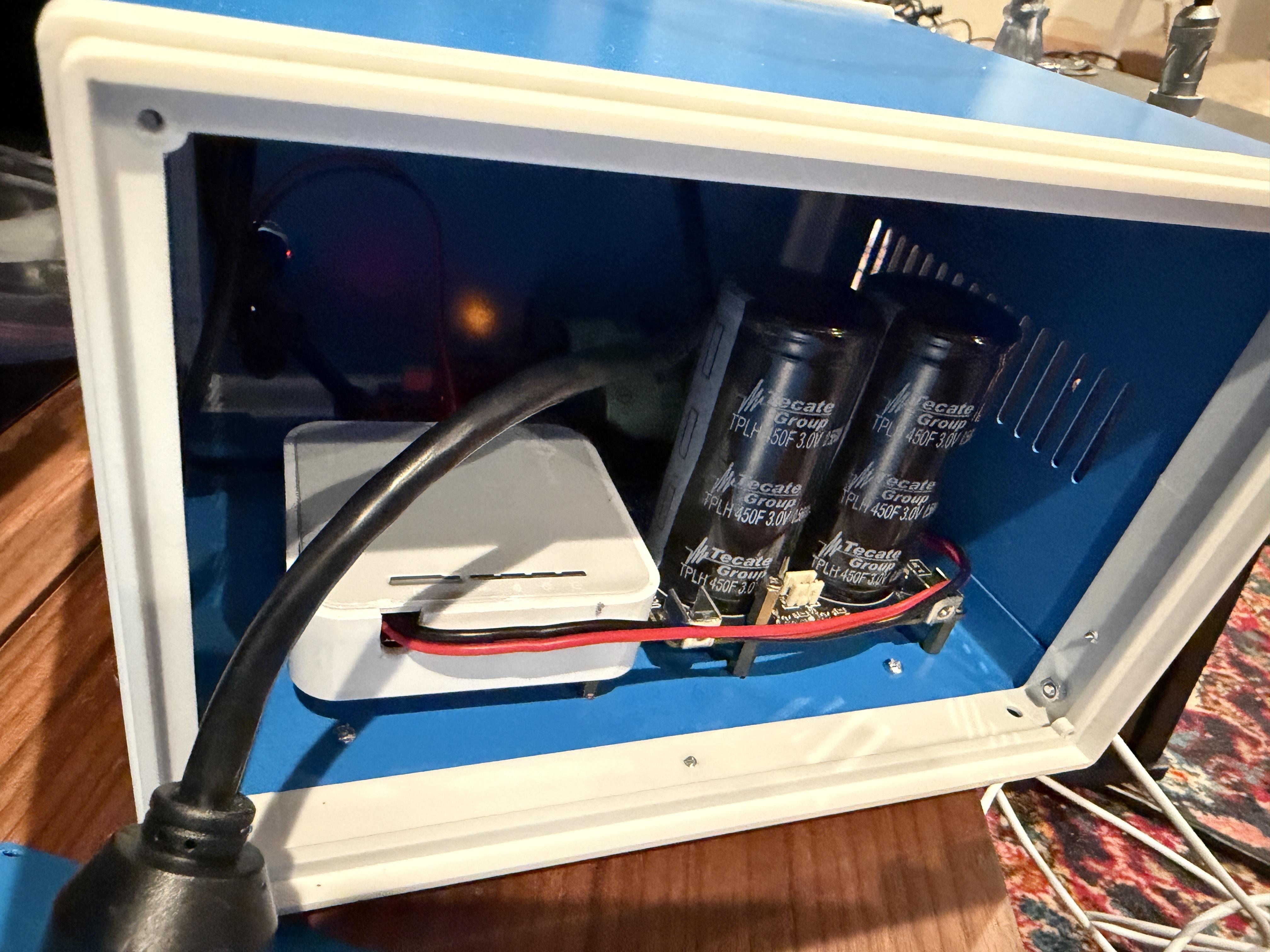
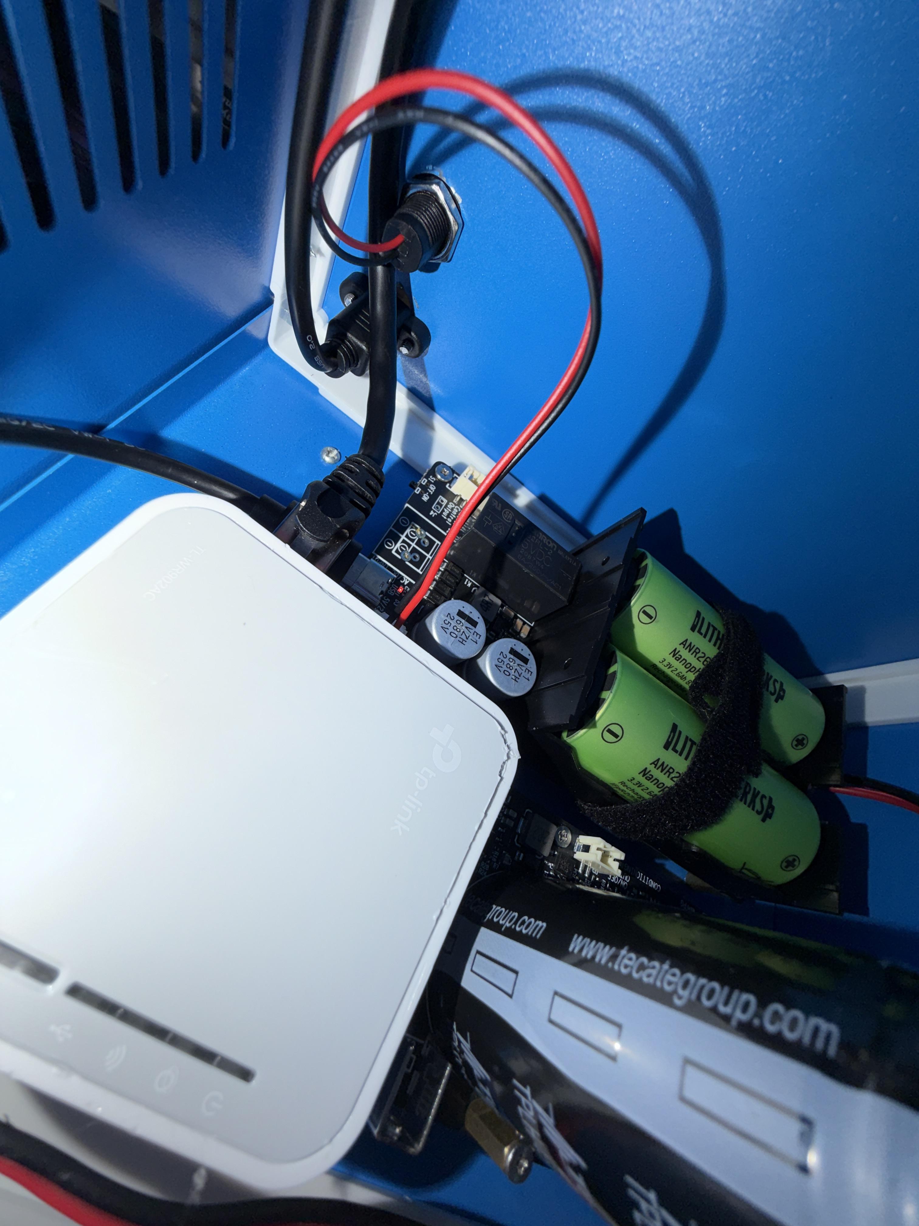
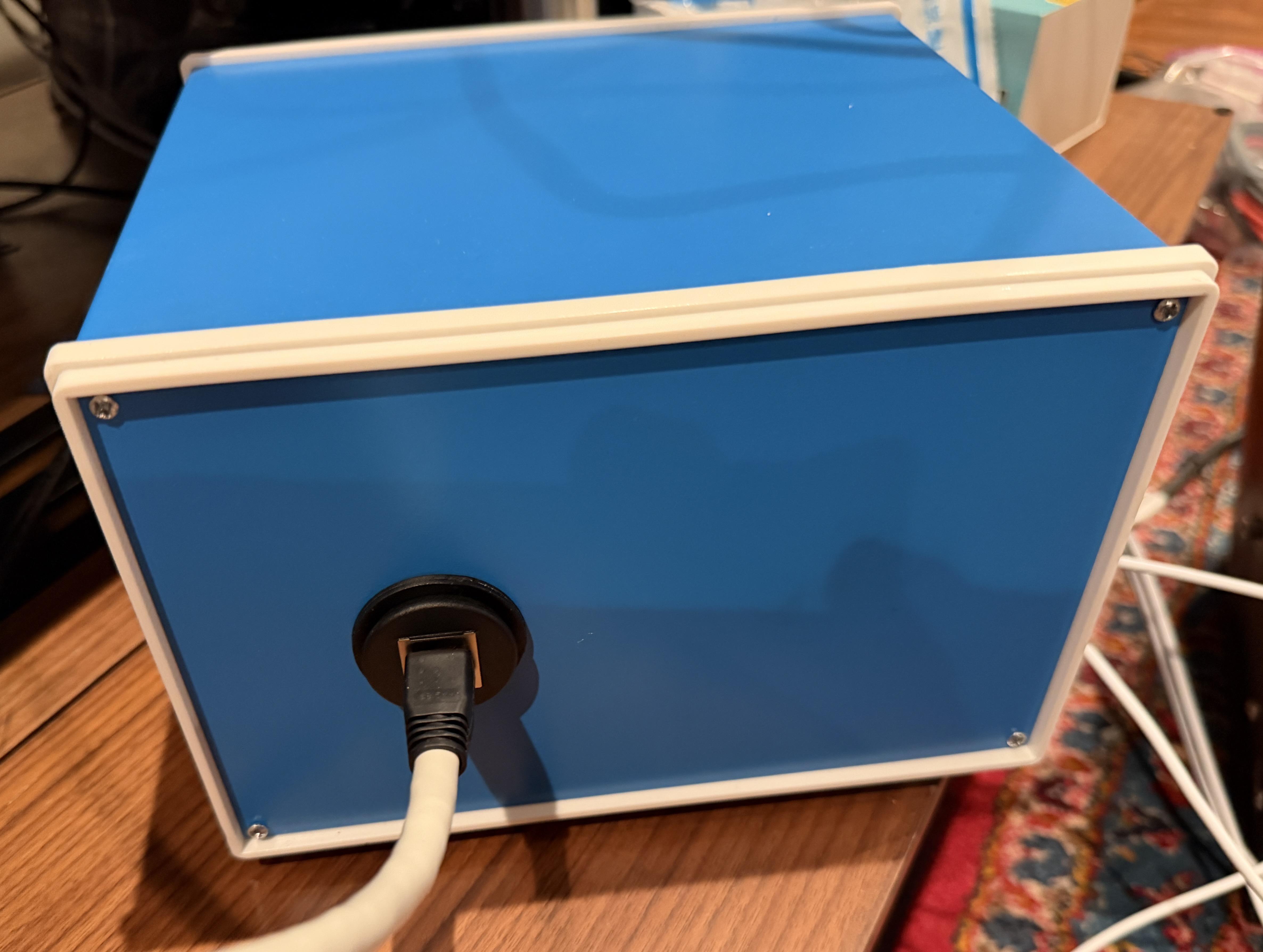
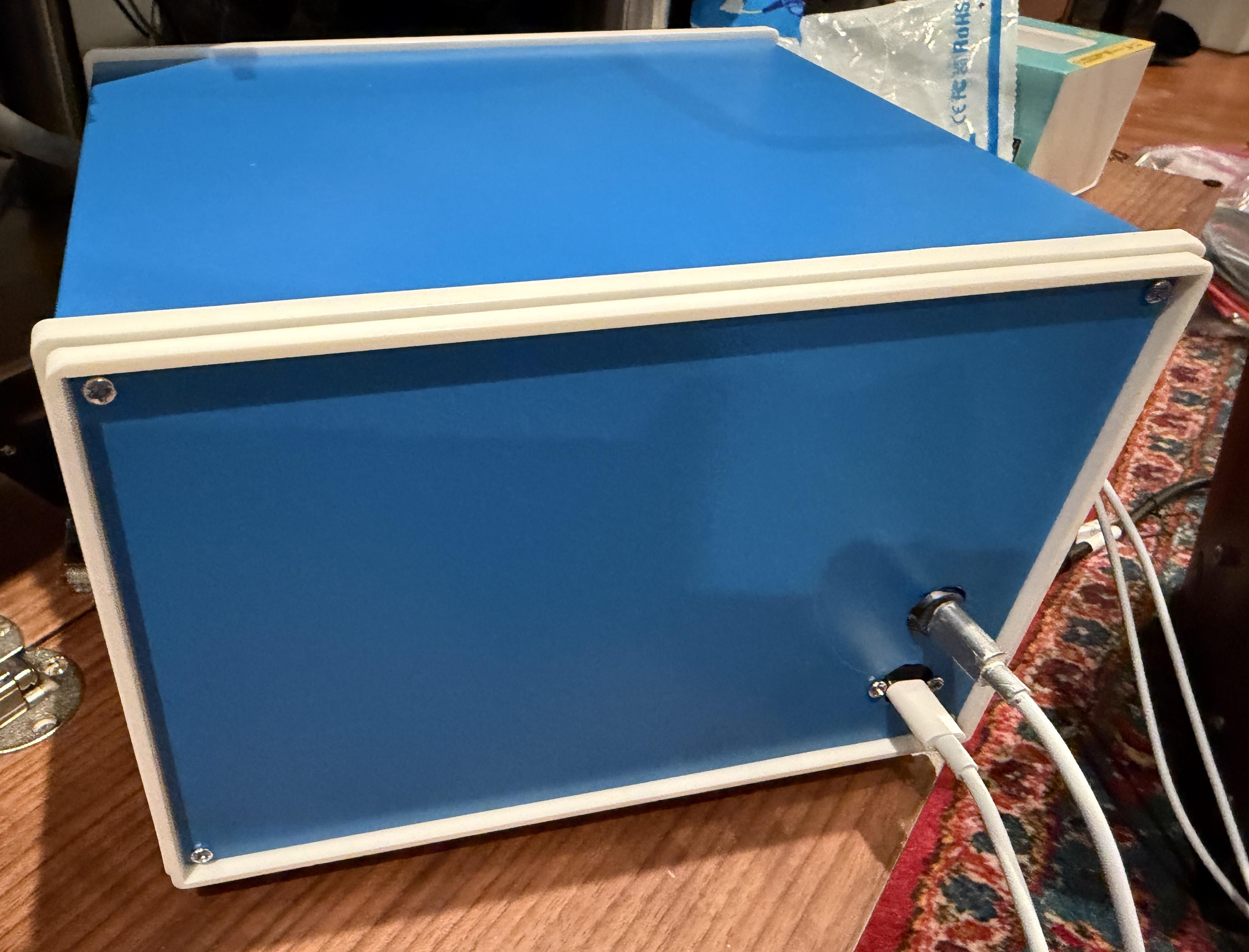
For the enclosure, I have one USB C input for charging, one switched USB C input for turning on and off, and ethernet output. I purchased standoff screws from Ian for the mini battery PCB, conditioner PCB, and the WR902 (I drilled mounting holes in the bottom of the case when I had the PCB out)
I am currently waiting on delivery of parts to build a v3 throttle cable. Looking forward to hearing what impact that has with the WR902
As an aside, note that Ian let me know that a new Pro version of the LiFEPO4 mini battery adapter is getting close to release, that support faster USB charging and have some other improvements
November 10, 2025 um 06:22 Uhr #5325@rghanbari Sounds awesome. Can you share some photos please of your build?
November 10, 2025 um 08:14 Uhr #5326@Eric – vielen Dank für den Hinweis. Das war auf den Bildern vom Board nicht ersichtlich, dass dort bei S1 schon ein Schiebeschalter verbaut ist. Über diesen Schalter s1 schalte ich also den 3,3 v Output zum TP Link ein/aus, richtig? Ich würde nämlich gern den TP Link nach jeder Hörsession komplett stromlos schalten. Hätte ein externer Schalter bei J4 die gleiche Funktion?
Beste Grüße. Torsten
@rghanbari: Thanks a lot. Sounds to comlicate for me. Brgds TorstenNovember 10, 2025 um 09:14 Uhr #5327@Eric: Sorry für meine nachfolgende Frage. Die unten markierte Steckbuchse auf dem Board kann ich nicht für den Einbau eines separaten Schalters für den on/off des 3,3 v outputs zum TP Link nutzen? Ich müsste dann direkt bei S4 Kabel für einen Schalter auf die Platine löten? Gruß. Torsten
Attachments:
You must be logged in to view attached files.November 10, 2025 um 20:02 Uhr #5329Hallo Torsten,
meines Wissens wird ein Kabel mit einem Stecker für die Buchse J4 mitgeliefert.
An dieses Kabel kannst Du dann einen Schalter anlöten, wenn du das Board in ein Gehäuse baust und nicht an den fertig eingebauten S1 Schiebeschalter kommst.Beste Grüsse,
Eric
November 10, 2025 um 20:59 Uhr #5330Hallo Eric,
genauso wollte ich das machen. Danke für deine Hilfe.
Viele Grüße. Torsten
November 11, 2025 um 00:14 Uhr #5331 November 11, 2025 um 00:14 Uhr #5332
 November 11, 2025 um 00:15 Uhr #5333
 November 11, 2025 um 00:16 Uhr #5334
 November 11, 2025 um 00:28 Uhr #5335
Thank you for the pictures. Did you find any Wifi signal attenuation by the enclosure? Why close the TPLink box back after you opened it up?
November 11, 2025 um 00:43 Uhr #5336I have pretty good WiFi in my home (3 access points), so I wasn’t able to detect any signal attenuation (signal strength stayed „excellent“)
Originally my plan was to have the extender PCB mounted bare to the enclosure, but there wasn’t a convenient mounting point on the PCB. Instead I added standoffs to the lower plastic case. After that, I put the cover back on because the plastic tabs on the cover keep the extender PCB in place.
If you have a convenient way to mount the extender PCB direct to the case that would make things cleaner. Given all the experiments/hacks I did before getting my enclosure, this was the easiest (incremental) path for me.
Dezember 3, 2025 um 08:39 Uhr #5353Here is my IanCanada UCPurePro 2025 build. Input transformer for a 12V inputs CMChoker filtration, then the 3000F ultracap system. Final step for this polycarbonate case is I drilled holes in the TPlink housing so I can screw it directly to the enclosure with a cutout to allow direct LAN attachment.
Attachments:
You must be logged in to view attached files.Dezember 10, 2025 um 17:37 Uhr #5356Hallo KTC,
das sieht wirklich interessant aus.
Spannend zu sehen, das die Themen von hier teilweise weltweit aufgenommen wurden und weiter entwickelt werden.Beste Grüsse,
Eric
-
AutorBeiträge
- Du musst angemeldet sein, um auf dieses Thema antworten zu können.